iTop-br-power-infrastructure
User Guide
iTop-br-power-infrastructure
This guide provides a more detailed explanation of the data model, modeling principles, and recommended usage of the iTop-br-power-infrastructure extension.
It is intended for administrators, implementers, and advanced users who want to understand not only which classes are available, but also how they should be used together in a consistent and realistic way.
1. Introduction
iTop-br-power-infrastructure extends the native iTop CMDB model for documenting electrical power infrastructure.
The module is designed for environments such as:
- data centers
- server rooms
- technical facilities
- critical utility rooms
- electrical supply areas around IT systems
The extension makes it possible to document not only basic power dependencies, but also more structured and realistic topologies involving utility feeds, generators, transfer switches, UPS systems, distribution boards, PDUs, sockets, and downstream devices.
2. Design Goals
The extension is built around the following goals:
- provide a structured model for electrical power components
- improve documentation of technical power characteristics
- support simple and advanced power supply topologies
- remain compatible with selected native iTop power concepts
- allow more detailed rack-level power assignment through sockets
- make power relationships visible through generic topology links
The module is not intended to replace full building electrical engineering documentation. Instead, it focuses on the parts that are most relevant for IT infrastructure, service continuity, and structured CMDB-based documentation.
3. Modeling Approaches
The extension supports two complementary ways of modeling electrical relationships.
3.1 Native iTop power chain
The native iTop model already supports the relation:
PowerSource→PDU
This remains available for compatibility and can still be used where appropriate.
Typical use cases:
- simple environments
- compatibility with existing data
- existing implementations already based on
powerstart_id
3.2 Generic power topology links
The preferred topology model introduced by this extension is:
lnkPowerConnectionToPowerConnection
This allows directional links between PowerConnection objects and supports more realistic topologies such as:
- utility feed → transfer switch
- generator → transfer switch
- transfer switch → UPS
- UPS → distribution board
- distribution board → PDU
Typical use cases:
- more advanced power path documentation
- emergency power modeling
- multiple stages of distribution
- transfer switch input modeling
- documenting topology beyond the native
PowerSource→PDUrelation
3.3 Recommended approach
Use the generic link model as the preferred way to represent power flow between PowerConnection objects.
Keep the native PowerSource → PDU relation mainly for:
- compatibility
- legacy data
- simple installations where no intermediate topology is required
4. Core Classes
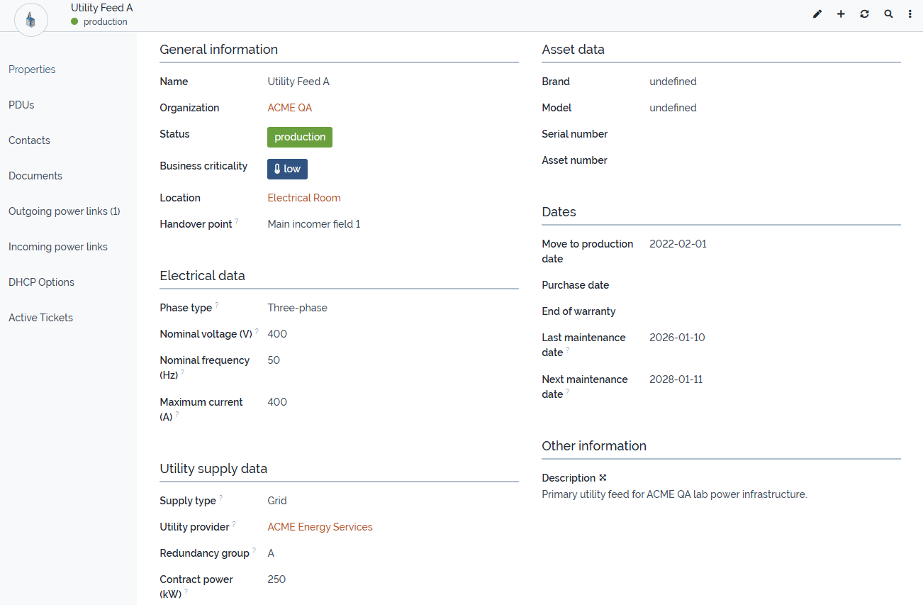
4.1 UtilityPower
UtilityPower is a dedicated class derived from PowerSource.
It is intended to represent the normal upstream or external power supply, for example:
- public grid connection
- building feed
- external feed
- temporary feed
Typical attributes:
supply_typeutility_provider_idredundancy_groupcontract_power_kwhandover_point
Typical usage:
- model the normal incoming power supply
- document the technical handover point
- distinguish between redundant supply paths such as feed A and feed B
Screenshot reference
4.2 UPS
UPS is a dedicated class derived from PowerSource.
It is used to represent uninterruptible power supplies that protect downstream systems.
Typical attributes:
ups_topologyrated_power_varated_power_wattautonomy_time
Typical usage:
- document online, line-interactive, or other UPS systems
- connect upstream and downstream power paths
- assign related battery units through
batteries_list
4.3 UPSBattery
UPSBattery is a dedicated class derived from PhysicalDevice.
It is used to document battery units assigned to a UPS.
Typical attributes:
ups_idbattery_rolebattery_typebattery_statusbattery_voltagebattery_capacity_ahlast_replacement_datenext_replacement_date
Typical usage:
- document internal or external battery units
- track replacement cycles
- document health state and battery technology
4.4 PowerGenerator
PowerGenerator is a dedicated class derived from PowerSource.
It is used to document emergency generators or other backup power units.
Typical attributes:
generator_typefuel_typerated_power_kvafuel_tank_capacity_lfuel_consumption_lphautonomy_timestart_methodis_ats_availablelast_test_datenext_test_date
Typical usage:
- document backup generation capacity
- model generator input to a transfer switch
- track test intervals and fuel characteristics
4.5 PowerTransferSwitch
PowerTransferSwitch is a dedicated class derived from PowerConnection.
It is used to represent switching components between multiple power inputs and a downstream load path.
Typical attributes:
switch_type
Typical usage:
- model switching between utility supply and generator supply
- represent automatic, manual, static, or bypass switching elements
- use
primary_inputandsecondary_inputas incoming link roles
Screenshot references
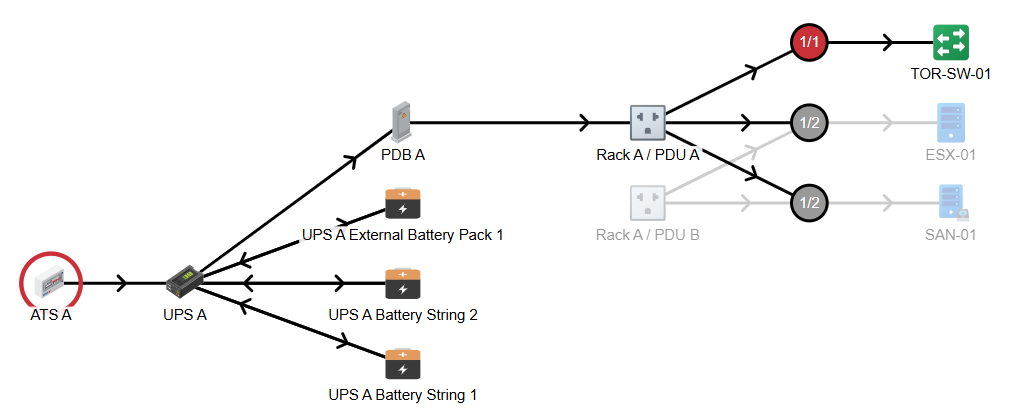
4.6 PowerDistributionBoard
PowerDistributionBoard is a dedicated class derived from PowerConnection.
It is used to represent electrical distribution stages between upstream sources and downstream consumers.
Typical attributes:
board_typeredundancy_groupnumber_of_outgoing_feeds
Typical usage:
- model main distributions and sub-distributions
- represent critical load panels
- structure the power path between UPS, PDU, and downstream devices
4.7 PowerSocketType
PowerSocketType is a typology class used to standardize socket formats.
Typical usage:
- IEC C13
- IEC C19
- other standardized outlet formats
This class is optional but recommended where socket standardization is useful.
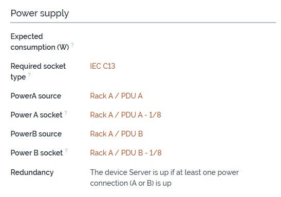
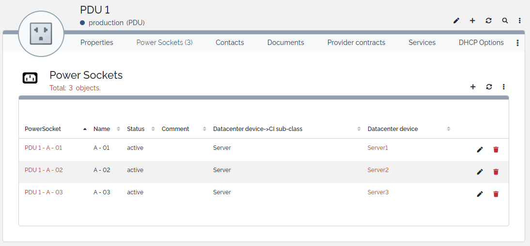
4.8 PowerSocket
PowerSocket represents an individual physical outlet on a PDU.
Each socket:
- belongs to exactly one
PDU - may be assigned to one
DatacenterDevice - can represent Power A or Power B on the connected device
Typical usage:
- document outlet-level power assignment
- link rack devices to specific PDU outlets
- show rack-level downstream dependencies
4.9 lnkPowerConnectionToPowerConnection
This generic link class is used to model directional relationships between PowerConnection objects.
Typical attributes:
source_powerconnection_idtarget_powerconnection_idlink_rolecomment
This class is the preferred mechanism for modeling generic power flow.
5. Link Roles and Recommended Usage
5.1 General rule
Always model power paths from source to target.
This means:
- upstream object = source
- downstream object = target
5.2 Recommended roles
downstream
Use downstream as the recommended generic role for standard source-to-target power flow.
Typical examples:
- transfer switch → UPS
- UPS → distribution board
- distribution board → PDU
- utility feed → distribution board
primary_input
Use primary_input for the preferred normal input of a transfer switch.
Typical example:
- utility feed → transfer switch
secondary_input
Use secondary_input for the backup or alternate input of a transfer switch.
Typical example:
- generator → transfer switch
bypass
Use bypass only where a meaningful alternate or bypass path must be documented.
other
Use other only for exceptional or project-specific cases that do not fit the standard roles.
5.3 Modeling recommendation
Keep the use of link roles as simple and consistent as possible.
For most normal source-to-target relationships, use:
downstream
Use primary_input and secondary_input specifically for transfer switch input modeling.
6. PowerSocket and DatacenterDevice Logic
The module adds dedicated socket handling between:
PDUPowerSocketDatacenterDevice
6.1 Power A / Power B assignment
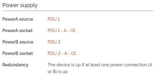
Each DatacenterDevice can be linked to:
- one Power A socket
- one Power B socket
6.2 Assignment behavior
The module ensures that:
- a socket can only be assigned to one device at a time
- socket assignment is synchronized in both directions
- sockets are connected and disconnected consistently during updates and deletions
6.3 Typical usage
- connect redundant devices to two different PDUs
- document outlet-level power usage
- make rack power dependencies transparent
Screenshot references
7. Example Topologies
7.1 Basic protected path
graph TD
    UtilityPower[UtilityPower]
    TransferSwitch[PowerTransferSwitch]
    UPS[UPS]
    PDU[PDU]
    Device[DatacenterDevice]

    UtilityPower -->|primary_input| TransferSwitch
    TransferSwitch -->|downstream| UPS
    UPS -->|downstream| PDU
    PDU --> Device
7.2 Emergency power path with generator and distribution stage
graph TD
    UtilityPower[UtilityPower]
    Generator[PowerGenerator]
    TransferSwitch[PowerTransferSwitch]
    UPS[UPS]
    DistributionBoard[PowerDistributionBoard]
    PDU[PDU]
    Socket[PowerSocket]
    Device[DatacenterDevice]

    UtilityPower -->|primary_input| TransferSwitch
    Generator -->|secondary_input| TransferSwitch
    TransferSwitch -->|downstream| UPS
    UPS -->|downstream| DistributionBoard
    DistributionBoard -->|downstream| PDU
    PDU --> Socket
    Socket --> Device
7.3 Demo data usage
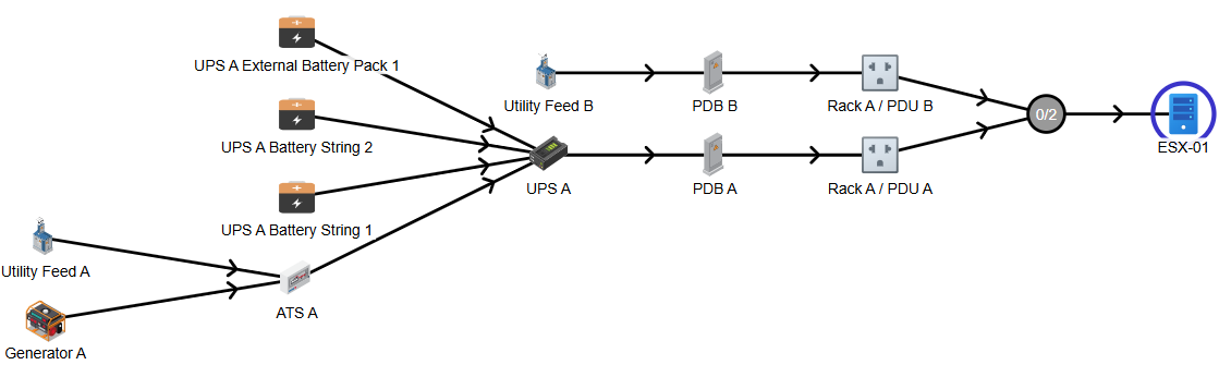
The existing demo data used during development already reflects a realistic topology that can be used for:
- testing UI behavior
- validating relations
- producing screenshots
- verifying upgrade behavior
- demonstrating protected and unprotected supply paths
This means the screenshots already referenced in the project documentation can also be reused as practical visual examples for this guide.
8. Relations and Dependency View
The extension uses different kinds of relationships.
8.1 Ownership and assignment relations
Examples:
UPSownsUPSBatteryPDUownsPowerSocketPowerSocketmay be assigned to aDatacenterDevice
8.2 Generic topology relations
Examples:
UtilityPower→PowerTransferSwitchPowerTransferSwitch→UPSUPS→PowerDistributionBoardPowerDistributionBoard→PDU
These are modeled through lnkPowerConnectionToPowerConnection.
8.3 Native compatibility relation
Example:
PowerSource→PDU
This remains supported for compatibility, but the preferred model for more flexible topologies is the generic link model.
Screenshot references
9. Upgrade and Migration Notes
9.1 Migration of legacy powerstart_id
From version 2.0.0, the installer imports existing legacy PDU.powerstart_id relations into the generic link model.
This means that existing legacy PowerSource → PDU assignments are automatically duplicated as:
source_powerconnection_id = powerstart_idtarget_powerconnection_id = PDU.idlink_role = downstream
9.2 Migration of output to downstream
From version 2.0.0, existing generic topology links using the role output are migrated to:
downstream
Duplicate downstream links are not created. If a matching downstream link already exists, the obsolete output link is removed during migration.
Menu overview
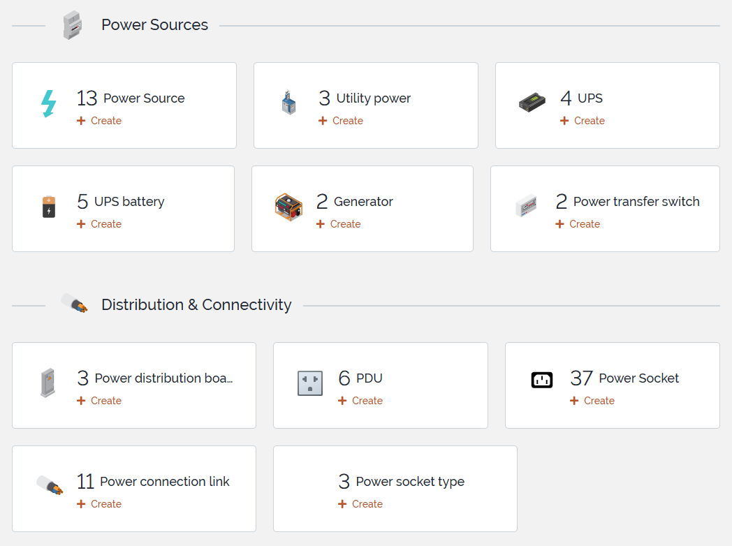
This screenshot gives a compact overview of the main business classes introduced by the extension.
11. Modeling Recommendations
Recommended
- use
downstreamas the default generic source-to-target role - use
primary_inputandsecondary_inputonly for transfer switch input modeling - keep naming and object roles consistent across the topology
- use
PowerSocketTypewhere socket standardization matters - prefer the generic link model for advanced topologies
- reuse the existing demo data as the reference dataset for screenshots and validation
Avoid when possible
- mixing too many role interpretations in the same topology
- overusing
other - treating the legacy native power chain and the generic topology model as equal primary modeling approaches in complex environments
12. Final Notes
iTop-br-power-infrastructure is intended to provide a structured and extensible foundation for documenting electrical power infrastructure around IT environments.
The current model already supports a useful range of real-world scenarios, from simple power source to PDU documentation up to more advanced chains involving utility feeds, generators, transfer switches, UPS systems, distribution boards, and socket-level device assignment.
The existing screenshots and demo data already provide a strong basis for documentation, validation, and practical usage guidance.